
|
Designation |
Boundary Dimension |
Mounting Hole Size |
Gear Data |
Basic load ratings |
Mass |
||||||||||||||||
|
No Gear |
External Gear |
Internal Gear |
D |
d |
H |
D1 |
D2 |
n |
Φ |
m |
Da |
Z |
da |
Z |
b |
x |
Coa(10KN) |
(Kg) |
|||
| 010.30.500 | 011.30.500 | 013.30.500 | 602 | 398 | 80 | 566 | 434 | 20 | 18 | 5 | 630 | 123 | 365 | 74 | 60 | 0.5 | 129 | 75.8 | |||
| 012.30.500 | 014.30.500 | 602 | 398 | 80 | 566 | 434 | 20 | 18 | 6 | 630 | 102 | 366 | 62 | 60 | 0.5 | 129 | 75.8 | ||||
| 010.30.560 | 011.30.560 | 013.30.560 | 662 | 458 | 80 | 626 | 494 | 20 | 18 | 5 | 690 | 135 | 425 | 86 | 60 | 0.5 | 144 | 94 | |||
| 012.30.560 | 014.30.560 | 662 | 458 | 80 | 626 | 494 | 20 | 18 | 6 | 690 | 112 | 427 | 72 | 60 | 0.5 | 144 | 94 | ||||
| 010.30.630 | 011.30.630 | 013.30.630 | 732 | 528 | 80 | 696 | 564 | 24 | 18 | 6 | 774 | 126 | 492 | 83 | 60 | 0.5 | 187 | 110 | |||
| 012.30.630 | 014.30.630 | 732 | 528 | 80 | 696 | 564 | 24 | 18 | 8 | 776 | 94 | 488 | 62 | 60 | 0.5 | 187 | 110 | ||||
| 010.30.710 | 011.30.710 | 013.30.710 | 812 | 608 | 80 | 776 | 644 | 24 | 18 | 6 | 852 | 139 | 570 | 86 | 60 | 0.5 | 212 | 120 | |||
| 012.30.710 | 014.30.710 | 812 | 608 | 80 | 776 | 644 | 24 | 18 | 8 | 856 | 104 | 568 | 72 | 60 | 0.5 | 212 | 120 | ||||
| 010.40.800 | 011.40.800 | 013.40.800 | 922 | 678 | 100 | 878 | 722 | 30 | 22 | 8 | 968 | 118 | 632 | 80 | 80 | 0.5 | 313 | 256 | |||
| 012.40.800 | 014.40.800 | 922 | 678 | 100 | 878 | 722 | 30 | 22 | 10 | 970 | 94 | 630 | 64 | 80 | 0.5 | 313 | 256 | ||||
| 010.40.900 | 011.40.900 | 013.40.900 | 1022 | 778 | 100 | 978 | 822 | 30 | 22 | 8 | 1064 | 130 | 736 | 93 | 80 | 0.5 | 355 | 240 | |||
| 012.40.900 | 014.40.900 | 1022 | 778 | 100 | 978 | 822 | 30 | 22 | 10 | 1070 | 104 | 730 | 74 | 80 | 0.5 | 355 | 240 | ||||
| 010.40.1000 | 011.40.1000 | 013.40.1000 | 1122 | 878 | 100 | 1078 | 922 | 36 | 22 | 10 | 1190 | 116 | 820 | 83 | 80 | 0.5 | 394 | 305 | |||
| 012.40.1000 | 014.40.1000 | 1122 | 878 | 100 | 1078 | 922 | 36 | 22 | 12 | 1188 | 96 | 816 | 69 | 80 | 0.5 | 394 | 305 | ||||
| 010.40.1120 | 011.40.1120 | 013.40.1120 | 1242 | 998 | 100 | 1198 | 1042 | 36 | 22 | 10 | 1300 | 127 | 940 | 95 | 80 | 0.5 | 443 | 300 | |||
| 012.40.1120 | 014.40.1120 | 1242 | 998 | 100 | 1198 | 1042 | 36 | 22 | 12 | 1308 | 106 | 936 | 79 | 80 | 0.5 | 443 | 300 | ||||
| 010.45.1250 | 011.45.1250 | 013.45.1250 | 1390 | 1110 | 110 | 1337 | 1163 | 40 | 26 | 12 | 1449.5 | 118 | 1048.8 | 88 | 90 | 0.5 | 554 | 420 | |||
| 012.45.1250 | 014.45.1250 | 1390 | 1110 | 110 | 1337 | 1163 | 40 | 26 | 14 | 1453.2 | 101 | 1041.6 | 75 | 90 | 0.5 | 554 | 420 | ||||
| 010.45.1400 | 011.45.1400 | 013.45.1400 | 1540 | 1260 | 110 | 1487 | 1313 | 40 | 26 | 12 | 1608 | 131 | 1188 | 100 | 90 | 0.5 | 617 | 480 | |||
| 012.45.1400 | 014.45.1400 | 1540 | 1260 | 110 | 1487 | 1313 | 40 | 26 | 14 | 1610 | 112 | 1190 | 86 | 90 | 0.5 | 617 | 480 | ||||
| 010.45.1600 | 011.45.1600 | 013.45.1600 | 1740 | 1460 | 110 | 1687 | 1513 | 45 | 26 | 14 | 1820 | 127 | 1386 | 100 | 90 | 0.5 | 702 | 550 | |||
| 012.45.1600 | 014.45.1600 | 1740 | 1460 | 110 | 1687 | 1513 | 45 | 26 | 16 | 1824 | 111 | 1376 | 87 | 90 | 0.5 | 702 | 550 | ||||
| 010.45.1800 | 011.45.1800 | 013.45.1800 | 1940 | 1660 | 110 | 1887 | 1713 | 45 | 26 | 14 | 2016 | 141 | 1568 | 113 | 90 | 0.5 | 793 | 610 | |||
| 012.45.1800 | 014.45.1800 | 1940 | 1660 | 110 | 1887 | 1713 | 45 | 26 | 16 | 2016 | 123 | 1568 | 99 | 90 | 0.5 | 793 | 610 | ||||
| 010.60.2000 | 011.60.2000 | 013.60.2000 | 2178 | 1825 | 144 | 2110 | 1891 | 48 | 33 | 16 | 2272 | 139 | 1728 | 109 | 120 | 0.5 | 1210 | 1100 | |||
| 012.60.2000 | 014.60.1400 | 2178 | 1825 | 144 | 2110 | 1891 | 48 | 33 | 18 | 2268 | 123 | 1728 | 97 | 120 | 0.5 | 1210 | 1100 | ||||
| 010.60.2240 | 011.60.2240 | 013.60.2240 | 2418 | 2065 | 144 | 2350 | 2131 | 48 | 33 | 16 | 2496 | 153 | 1984 | 125 | 120 | 0.5 | 1350 | 1250 | |||
| 012.60.2240 | 014.60.2240 | 2418 | 2065 | 144 | 2350 | 2131 | 48 | 33 | 18 | 2502 | 136 | 1980 | 111 | 120 | 0.5 | 1350 | 1250 | ||||
| 010.60.2500 | 011.60.2500 | 013.60.2500 | 2678 | 2325 | 144 | 2610 | 2391 | 56 | 33 | 18 | 2772 | 151 | 2232 | 125 | 120 | 0.5 | 1500 | 1400 | |||
| 012.60.2500 | 014.60.2500 | 2678 | 2325 | 144 | 2610 | 2391 | 56 | 33 | 20 | 2780 | 136 | 2220 | 112 | 120 | 0.5 | 1500 | 1400 | ||||
| 010.60.2800 | 011.60.2800 | 013.60.2800 | 2978 | 2625 | 144 | 2910 | 2691 | 56 | 33 | 18 | 3078 | 168 | 2520 | 141 | 120 | 0.5 | 1680 | 1600 | |||
| 012.60.2800 | 014.60.2800 | 2978 | 2625 | 144 | 2910 | 2691 | 56 | 33 | 20 | 3080 | 151 | 2520 | 127 | 120 | 0.5 | 1680 | 1600 | ||||
| 010.75.3150 | 011.75.3150 | 013.75.3150 | 3376 | 2922 | 174 | 3286 | 3014 | 56 | 45 | 20 | 3480 | 171 | 2820 | 142 | 150 | 0.5 | 2380 | 2800 | |||
| 012.75.3150 | 014.75.3150 | 3376 | 2922 | 174 | 3286 | 3014 | 56 | 45 | 22 | 3476 | 115 | 2816 | 129 | 150 | 0.5 | 2380 | 2800 | ||||
| 010.75.3550 | 011.75.3550 | 013.75.3550 | 3776 | 3322 | 174 | 3686 | 3414 | 56 | 45 | 20 | 3880 | 191 | 3220 | 162 | 150 | 0.5 | 2690 | 3200 | |||
| 012.75.3550 | 014.75.3550 | 3776 | 3322 | 174 | 3686 | 3414 | 56 | 45 | 22 | 3894 | 174 | 3212 | 147 | 150 | 0.5 | 2690 | 3200 | ||||
| 010.75.4000 | 011.75.4000 | 013.75.4000 | 4226 | 3772 | 174 | 4136 | 3864 | 60 | 45 | 22 | 4334 | 194 | 3652 | 167 | 150 | 0.5 | 3020 | 3600 | |||
| 012.75.4000 | 014.75.4000 | 4226 | 3772 | 174 | 4136 | 3864 | 60 | 45 | 25 | 4350 | 171 | 3650 | 147 | 150 | 0.5 | 3020 | 3600 | ||||
| 010.75.4500 | 011.75.4500 | 013.75.4500 | 4726 | 4272 | 174 | 4636 | 4364 | 60 | 45 | 22 | 4835.6 | 217 | 4166.8 | 190 | 150 | 0.5 | 3410 | 4000 | |||
| 012.75.4500 | 014.75.4500 | 4726 | 4272 | 174 | 4636 | 4364 | 60 | 45 | 25 | 4845 | 191 | 4160 | 167 | 150 | 0.5 | 3410 | 4000 | ||||
The design’s of all these slewing rings are based on standard structures; LYNBC can design and manufacture many other similar structures in accordance to the special and particular requirements of their customers. If our customers have specific requests then the customer should identify the structure, and mounting dimensions that are required. Please contact the LYNBC Technical center if you need any assistance in this area.
Four-point contact ball slewing bearing
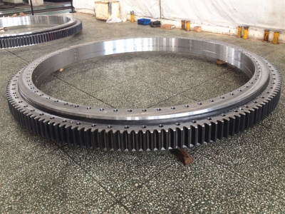
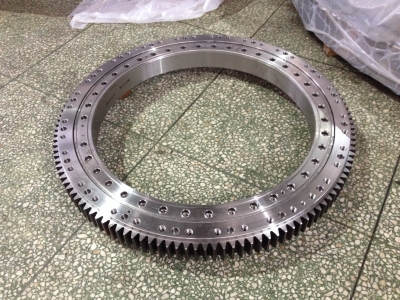
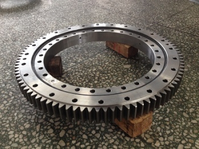
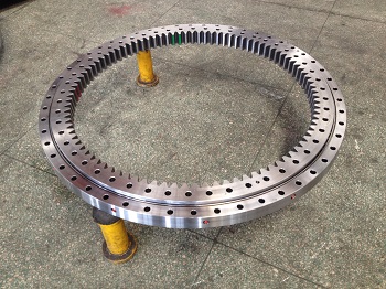
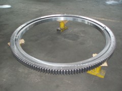
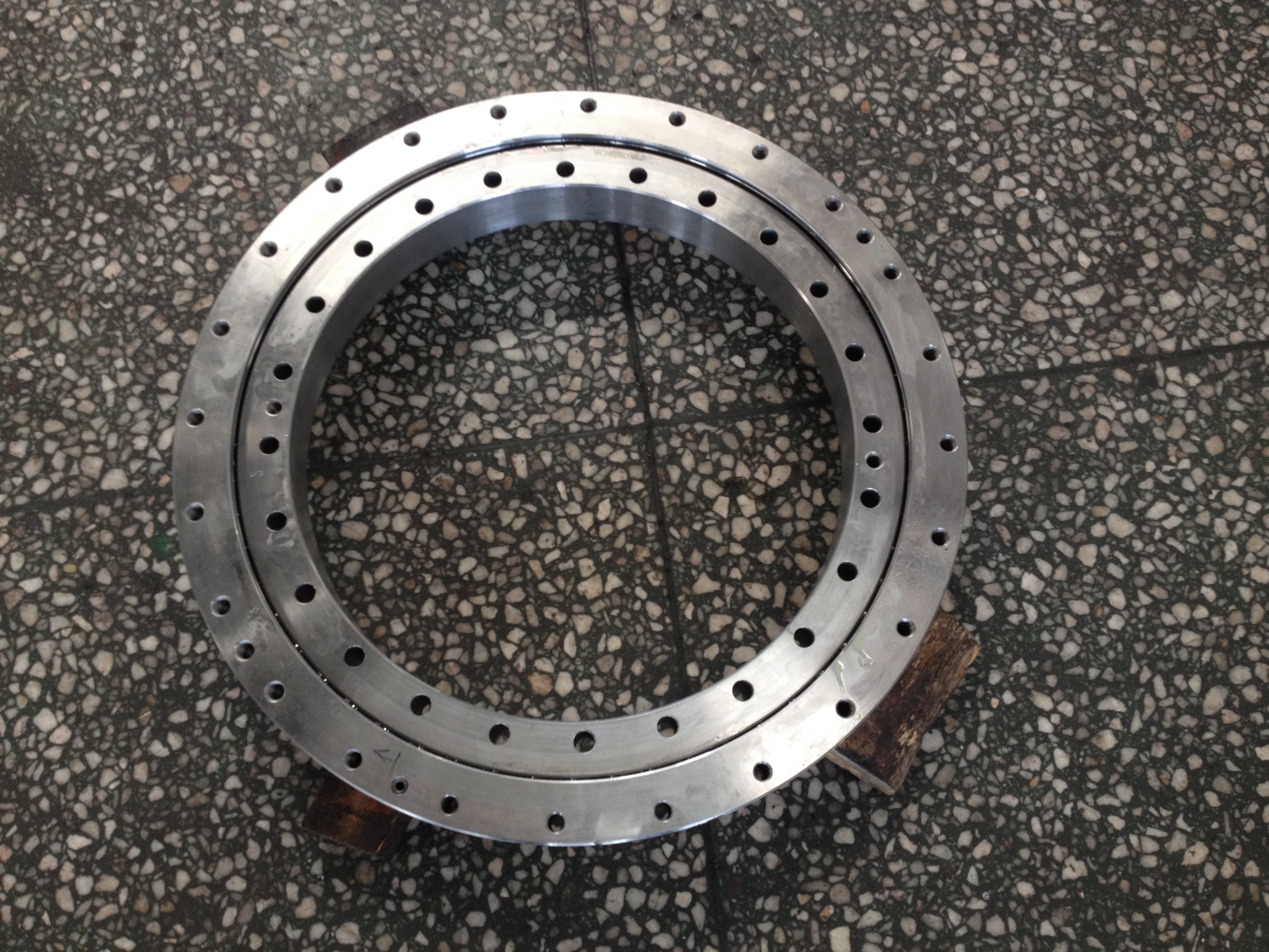
LYNBC Four-point contact ball slewing bearing can carry axial loads, tilting moment and radial loads all at the same time. Almost all steel balls will carry load under the combined action of axial load and tilting moment load. Steel balls are in contact with the raceway of outer ring and inner on a single-point when carrying pure axial load.
When radial loads exceed a certain value there would be two points respectively for the contacting balls within the outer and inner raceway. Meanwhile, wear and friction moment would be large. The tilting moment and radial force loading in any kind of working conditions allow the contact angle to be adjusted accordingly.
LYNBC Four-point contact ball slewing bearing in the main consist of a inner ring, outer ring, a single row of steel balls, and a cage (or spacing block).
LYNBC Four-point contact ball slewing bearing inner ring, outer ring have integral and split structure. The rigidity of the integral rings is relatively good in holding its rigidity. The split structure is fastened by bolts, this facilitates for a more convenient adjustment process.
Normally LYNBC Four point contact ball slewing bearing have cages (or spacing blocks). The full ball types has a larger load carrying capacity. In some situations this type would be selected for heavy loading applications. However, this design has a high frictional resistance, this could cause nicks on all surface.
The mounting needs will suit mounting holes that are designed as straight hole, counter hole, thread blind hole, or thread through hole and etc.
This contact ball design slewing bearing is suitable under axial load, tilting moment and small frictional resistance applications. The contact mounting surface must have adequate radial rigidity.
The basic structures of LYNBC four-point contact ball slewing bearing as below:
Without gear
External gear
Internal gear
▲ The design’s of all these slewing bearing are based on standard structures; LYNBC can design and manufacture many other similar structures in accordance to the special and particular requirements of their customers’. If our customer’s have specific requests then the customer should identify the structure, and mounting dimensions that are required. Please contact the LYNBC Technical Center if you need any assistance in this area.

.jpg)


